Instanced geometry.
Instanced geometry is a special copy of an object that shares one instance of geometry. Creating an instanced clones of an objects has very specific benefit: when one object is been modified, all instanced clones changes too.
To make an instanced geometry copy, use Create\Copy tool. Make sure to expand it's advanced settings box and set Instance option On. Object created as an instanced copy looks exactly the same as generic copy. Actually it's just an object, with it's local axes, rendering technique, but both original and copy uses the same mesh. Don't consider that mesh "belongs" to original object and instacned copy "just refers" it. The mesh doesn't belong and both objects refer the mesh. If you delete original object, it's instaned copy will become a regular object with the mesh.
Open Files/les1_01.z3d file. This is an old file you have worked on - it contains half of the BMW mesh. Expand advanced settings box in Create\Copy tool, place checkmark near Instance and set "Interaction" to None (we don't need to move or rotate after coping). Then click once on BMW mesh. Objects list will now display two rows with "Surface" label - because there are two "Surface" objects now. Rename them to "1 half" and "2 half". Expand advanced settings box in Modify\Mirror tool; place checkmarks near Mirror matrix and Mirror geometry, remove checkmark near Base to pivot. Switch to World-X axes mode and click on any of the objects. You will have something like on the image on the right. There are two halfs of the car and one is flipped insideout.
Note that you can't flip it with Modify\Flip tool since this tool alters the mesh and flips every individual polygon (this will result in correct rendering of one object, but another will become flipped).
For this only reason, there is an option in rendering technique
that allows to render object flipped (it does not alters the mesh).
 Right-click on a flipped object and pick Properties in context menu.
Expand Rendering\Technique branch and place checkmark near Internal
Faces Flip like on the left image. You can also disable Flat Shaded
mode if you like. Now you have two halfs of the car and you can edit/create
mesh and see the whole complete car at the same moment. For example, I've extruded
front headlight on one half and can see how this will look on a whole car. Notice
on the right image that both left and right headlights are extruded, while only
one object have been edited.
Warning: There are no any internal bindings between instanced copies, so when modifying one mesh, others might not get updated or might be rendered incorrectly. To update all objects in scene, you can use View\Redraw All command in main menu (I have 'R' hotkey assigned to it). This forces all objects in scene to be updated.
Modelling rims.
Preparing.

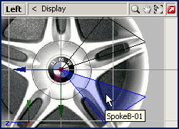
We shall modell 5 spokes wheel rim in this lesson. It's shown on the right image
and saved in file Files/rims.jpg. The idea of modelling rims is in usage
of "instanced geometry". We shall not model all five spokes - only one is needed.
Moreover, since each spoke is symmetrical, only a half of spoke need to be
modelled, like on the image below:

First of all, you need to compute angular degree for each spoke. 360 degress for
5 spokes is 72 degrees per each spoke.
Now, reset scene by File/New command and load Rims.jpg image into
left view backgound. Then create an object (create\surface\grid) that will be
a half of first spoke and shape it to single triangle as shown below (delete
unused and move remaining vertices):

Notice that local axes of this object are exactly in the center of the
wheel image. You can use Modify\Move tool with Move pivot only to
place local axes where needed.
Expand advanced settings box in Create\Copy tool, check "Instance"
and make sure "Interaction" is set to "None". Then click once on a spoke object.
Rename objects to "SpokeA-01" and "SpokeB-01". Now, expand advanced settings in
Modify\Mirror tool, check "Mirror Geometry", "Mirror Matrix" and uncheck
"Base to Pivot". Then switch to World-Y axes mode and click on one of the
objects. One spoke half will be mirrored and you'll get something like on the
image below:

We need to orient cloned copy by rotating it. The only limitation - mesh should
not change, so we are allowed to rotate whole object only (rotate it's geometry
and local axes at a time) as described below.
 Expand advanced settings box in Modify\Rotate tool, check "Rotate
Geometry", "Rotate Matrix" and uncheck "Base to pivot". With these options set
On, local axes will be rotated and thus geometry will rotate too. Make sure to
switch to World-X axes mode and rotate mirrored spoke until it comes where
it should be (you can hold
  key for more
accurate rotation). Image on the right shows how object should be rotated. Make
sure that original object stays unaffected by operations you perform.
Leave current axes mode, current options in Rotate tool and select these
two spokes objects. Now expand advanced settings box in Create\Copy tool
("Instance" is checked) and set "Interaction" type to "Rotate". From this moment
on, Copy tool will use Rotate interactive behavior. Switch to
selected mode, hold  key down and click in
left view. A quick rotation mode dialog box (it's standard Rotate tool behaviour when
Shift key is held down) will appear. Set our 72 degrees rotation value
and press Ok:
 You will have an instanced copies rotated and selected like on the right image.
Copy them again (they are selected) with 72 degrees rotation. And again two
times until you have all five spokes. Image below shows how it should look like:

Deselect all objects. On the image above I've highlighted the only object we shall
modify.
As you can see on the left image, half of objects are facing to the other side,
so "internal flip faces" options should be set on them. Select these objects,
switch to selected mode and pick Edit\Properties... in main menu (thus you
can change options for multiple objects at a time). Set Internal Faces Flip
in "Selection Properties" box and hit Ok. Now we shall set Flat shading
for all objects. Select all objects and like you did before, open "Selection
Properties" via main menu and checkmark "Flat Shading" option.
Notice on the right image that "Internal Flaces Flip" is dimmed for all objects.
This means that this option settings are currently differs for objects you've
selected (5 objects have this option set On and 5 set Off).
The file is here: Files/les3_01.z3d.
Shaping single spoke.
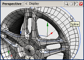
Switch "SpokeA-01" object (the one highlighted on the image above) to vertices level and start modelling half of the spoke in usual fashion. Remember to update other objects with Views\Redraw All if instanced clones don't update themselves. Note that you work with this object only (don't modify other objects). Also, don't try to weld vertices in the joints of these slices, just move vertices closer to each others.
Apply all you skill to achieve really cute-looking rims. When done, make sure
shading is fine (adjust it as usual). You can even set up environment reflections
onto default material if you like. Image below is what i've achieved:

Notice that I've highlighted a circle spline in viewport. I've created this
circle spline as a guide-line only (It helps to place vertices exactly on a
circular arc). Ok, the rims are almost done, the file is here:
Files/les3_02.z3d.
Making single object.
One of the most important thing is how to make single object out of these clones. You can not attach one to another and make single object, this will lead to incorrect result. Instead, you have to create non-instanced copies of all spokes and only these copies can be merged together.
So, pick Create\Copy tool, disable "Instance" option in it, enable "Move" interaction in it, and set axes mode to "World-X". Now select all these objects, switch to selected mode and drag them in front view aside. Standard copies will be created and dragged at this moment. Deselect them, select original (instanced) spokes and delete them. As you can see, half of spokes (those that used "Internal Flip Faces" option) are facing outside again. That's because they actually were outside-facing all this time. Now you can safely flip them with Modify\Flip tool. Recalculate normals if required and you are ready to merge these objects. Modify\Attach tool can do it for you. Attach one spoke to another to make single object of them (like on the right image). Then attach all other spokes one by one to this object.
Finally, you can weld vertices to make smooth shape where needed. Weld
tool in "multple target mode" can do it for you, just set proper distance
precision and normals angle values. If you were not too accurate (like me) while
modelled the rims you might face to some difficulties. Been a die hard modeller,
you can weld problematic vertices manually (if there are no that much of them).
Image below is what I've achieved:

The file is here: Files/les3_03.z3d.
Tips.
You can find the following tips useful when modelling your rims.
